Welding Concierge Function
Welding Concierge Function
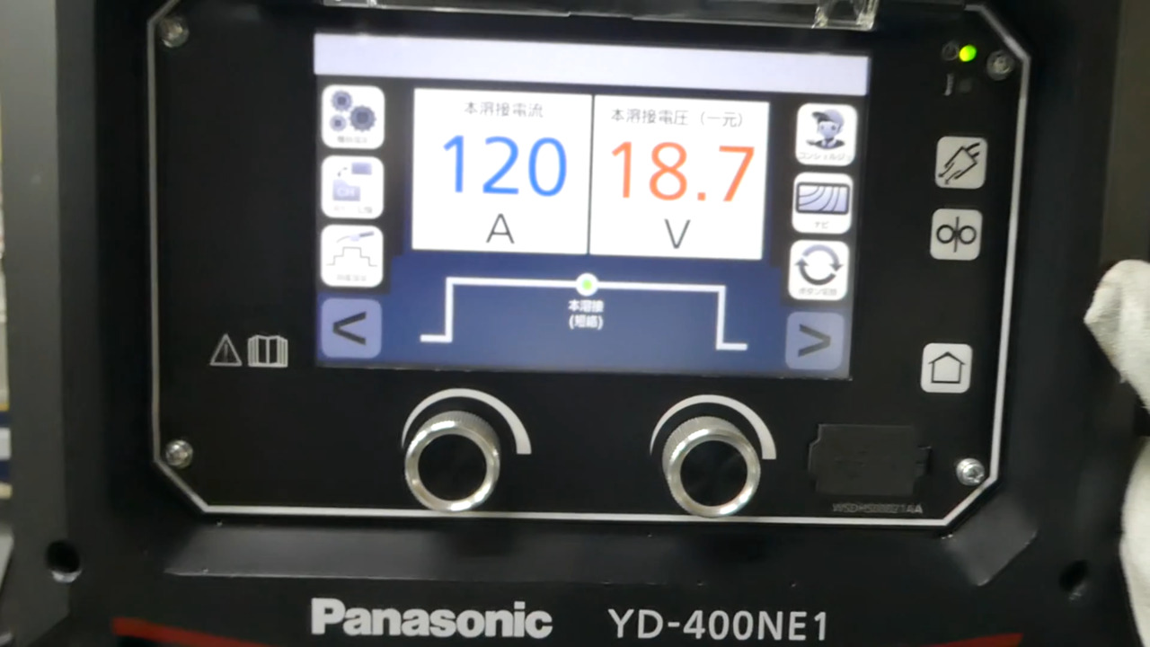
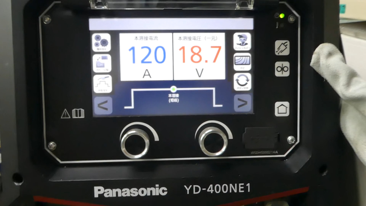
The YD-400NE1 semi-automatic welding machine is equipped with the "Welding Concierge" function to assist in solving various problems that may arise when welding.
By providing information on equipment configuration and specific wiring and other procedures prior to welding operation, this section is designed to help even first-time welder operators feel at ease.
This linkage page provides video and other content to make the information on the LCD display on the front of the welder even easier to understand. Please take a look at this page and make use of the information for your daily welding.
Inspection before welding operation
Inspection before welding operation
Refer to the following diagram for cable routing.
Ensure case grounding (grounding of the welder's outer box).
Make sure that the terminals and cables are not loosely connected. An incomplete connection will result in a poor connection, which will prevent normal operation and cause malfunction. If the fixing screw is tightened forcibly, the threads will be crushed and the screw cannot be tightened completely. Insert the fixing screws horizontally and tighten them with no excessive force.
Insulate cable connections and terminals with insulation tape or other means. Leaving energized parts exposed may cause electric shock or fire due to electrical leakage.
Do not bend the cable to an extreme. A bending diameter of less than 600 mm may significantly degrade welding performance.
About torches
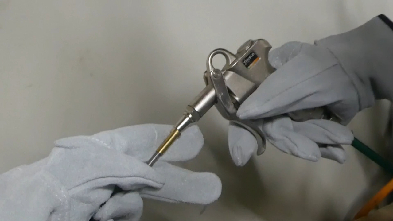
- Clean the liner and inner tube of dust, etc. with dry air. Accumulation of dust and shavings will deteriorate the wire feeding performance.
- If the tip is worn out, replace it with a new one. If the tip hole becomes worn and oval-shaped, current flow will be poor and the arc will be unstable.
- Tighten the tip securely with a monkey wrench or similar tool. Incomplete tightening of the tip may result in poor current flow, unstable arcs, or poking (the tip of the wire hitting the base metal).
- Remove any spatter adhering to the nozzle. If there is a lot of spatter on the nozzle, the shielding effect will be poor.
Tapping the torch to remove spatter will cause deformation or scratches on the nozzle, resulting in poor shielding effectiveness.
Use of an anti-spatter adhesion agent facilitates removal of spatter.
- Check the orifice. Forgetting to install it or use a cracked one will result in poor shielding effectiveness and cause pits or blowholes.
About wire and feeders
- The appropriate wire differs depending on the wire material and welding method, so please use the appropriate wire by referring to the table below
| Wire Material | Wire Type | Welding Method | Wire diameter (mm) |
Ver. | Spedific Ver | Protrusion length*. Setting of (mm) |
|---|---|---|---|---|---|---|
| Mild steel | Solid wire | CO2 | 0.8 | Standard | 10 | |
| 0.9 | Standard | 12 | ||||
| 1.0 | Standard | 15 | ||||
| 1.2 | Standard | (JIS Z 3312YGW12) | 15, 20 | |||
| 1.4 | 2.00 | (JIS Z 3312YGW11) | 20 | |||
| MAG | 0.8 | Standard | 10 | |||
| 0.9 | Standard | 12 | ||||
| 1.0 | Standard | 15 | ||||
| 1.2 | Standard | 15, 20 | ||||
| 1.4 | Standard | 20 | ||||
| Pulse MAG | 0.9 | Standard | 12 | |||
| 1.0 | Standard | 15 | ||||
| 1.2 | Standard | 15 | ||||
| 1.4 | Standard | 20 | ||||
| FCW (Flux Cored Wire) |
CO2 | 1.2 | Standard | 20 | ||
| 1.4 | Standard | 20 | ||||
| MAG | 1.2 | Standard | 20 | |||
| Stainless steel | Solid wire | MIG | 0.8 | Standard | 10 | |
| 0.9 | Standard | 12 | ||||
| 1.0 | Standard | 15 | ||||
| 1.2 | Standard | 15 | ||||
| Pulse MIG | 0.9 | Standard | 12 | |||
| 1.0 | Standard | 15 | ||||
| 1.2 | Standard | 15 | ||||
| FCW (Flux Cored Wire) |
CO2 | 0.9 | Standard | 12 | ||
| 1.2 | Standard | 20 | ||||
| MAG | 1.2 | Standard | 20 | |||
| Hard Aluminum | Solid wire | MIG | 1.0 | Standard | 15 | |
| 1.2 | Standard | 15 | ||||
| 1.6 | Standard | 20 | ||||
| Pulse MIG | 1.0 | Standard | 15 | |||
| 1.2 | Standard | 15 | ||||
| 1.6 | Standard | 20 | ||||
| Soft Aluminum | Solid wire | MIG | 1.2 | Standard | 15 | |
| 1.6 | Standard | 20 | ||||
| Pulse MIG | 1.2 | Standard | 15 | |||
| 1.6 | Standard | 20 | ||||
| Low Slag | Low Slag wire | Pulse MAG | 1.2 | Standard | 15 |
- Check the wire for rust and debris. Large amounts of rust or debris can cause welding defects.
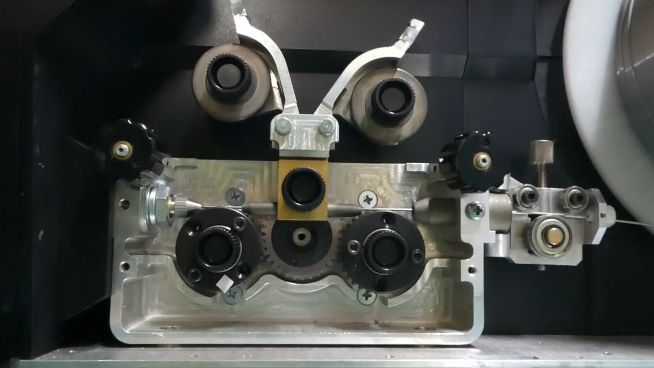
- Adjust the wire pressure appropriately. Weak pressure causes the wire to slip, resulting in poor feedability.
If the pressure is too strong, the wire will be damaged, resulting in poor feedability.
- Make sure you are using the correct roller or wire guide for the wire.
- Place the feeder in a position where it will not be hit by spatter. If spatter adheres to or scratches the wire, wire feeding performance will deteriorate and the arc will become unstable.
- Press the inching button to feed the wire.
About gas
- Fix the gas cylinder firmly.
- Use the appropriate gas regulator for the gas to be used. Different types of gases have different specific gravity and will not indicate the correct flow rate.
- The flow meter must be installed straight. If the flow meter is installed at an angle, it will not indicate the correct flow rate.
-
Do not bend the gas hose to an extreme.
-
Refer to the table for mixing ratios. Approximate gas flow rate is 15 L/min.
| About gas | For CO2 welding: CO2 100 % For MAG welding: Ar 80 % + CO2 20 % mixed gas(MAG gas) For sutainless steel MIG welding: Ar 98 % + O2 2 % mixed gas(MIG gas) For aluminum MIG welding: Ar 100 %(MIG gas) * [CO2 = carbon dioxide gas, Ar = argon gas, O2 =oxygen] |
|---|
- Set the pre-flow and after-flow time.
- Press the gas check button and check for gas.
Support
Global network
Panasonic has established a system to support customers all over the world. Customers expanding production from Japan to overseas factories can also use our equipment with peace of mind.
Website for Panasonic Shoyokai
Website dedicated page for members of Panasonic Shoyokai. You can download the application form to join the membership website P-Web.