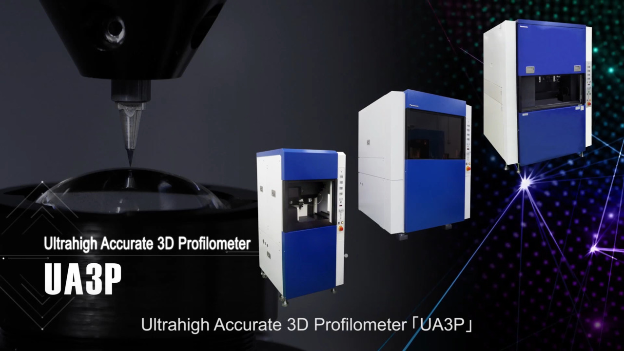
Ultrahigh Accurate 3-D Profilometer UA3P Series
Ultrahigh accurate 3-D profilometer (UA3P)
Main Features
- Ultra-accurate measurement with highest stability
- Automatic NC program generation
- Extensive library of optional software
"It is impossible to manufacture parts without making measurements" - The UA3P series supports nanometer-accuracy manufacturing by making precise measurements of various fine shapes.
UA3P can measure aspheric lenses, free curved surface mirrors, and molds for processing them with a maximum accuracy of 0.01 μm. These lenses and mirrors are indispensable for digital home appliances such as smartphones, DSCs, DVDs, and Blu-ray devices, home security, optical communication, automotive HUDs, etc. UA3P allows easy operations to achieve rapid processing feedback.
Ultrahigh accurate 3-D profilometer (UA3P)
Strengths and Features
Measurement range of the Ultrahigh Accurate 3-D Profilometer UA3P Series
Measurement accuracy and application fields of various types of profilometers
Offering a full profilometer series lineup ranging from an ultra-high precision measurement of ±0.10 μm at a 70° tilt angle to the measurement of large parts with a 500 mm square area
Measurement area and accuracy by model
A model that only allows side-surface measurement (UA3P-L) is also available.
Measured objects
| Lenses for mobile devices | Lens barrels | DSLR lenses |
|---|---|---|
|
|
|
|
| fθ lenses | X-ray telescope mirrors | Molds for lenses |
|
|
|
|
| Camera lenses | Molds for toric lenses | Stepper lenses |
|
|
|
|
Technology for realizing ultra-high precision measurements
Coordinate measurement technology
Coordinate measurement technology
The profilometer’s coordinate system is configured with three reference flat surfaces (mirrors) independent of the stages. The length of an object in each X, Y, and Z axis is measured to a resolution of 0.3 nm with the laser interference method using a He-Ne frequency-stabilized laser as a light source. This suppresses the influence of squareness and straightness of the stages to achieve high-precision measurement.
- Measurement error due to coordinate axes
0.05 µm max. (up to 100 mm)
0.3 µm max. (up to 500 mm)
Top surface measuring probe/AFP
High-precision scanning and measurement of a measured object is feasible due to the use of ultra-low measuring forces.
The stylus is held by a micro-air slider, and the focus laser detects the movement of the stylus. The position of the AFP is tracked in line with the shape of the measured object to keep the measuring force constant.
- Measuring force: 0.15 to 0.30 mN (15 to 30 mgf)
* UA3P-3000 applies a force of 0.10 to 0.20 mN. - Stylus: A diamond stylus with a tip angle of 30º and a radius of 2 µm can be used.
Side-surface measuring probe/S-AFP
The inclination of a probe mirror detected with high-precision is fed back to the XY stages to enable a scanning measurement with a low contact force (0.3 mN).
This enables measurement without deforming resin products, such as a lens cylinder (barrel).
- Measuring force: 0.3 mN (30 mgf)
- Measurement accuracy: ±0.15 µm (when measuring 90º inclination)
- Maximum measurement angle
Horizontal measurement: 45º to 90º (angle relative to the horizontal surface)
Vertical measurement: 80º to 90º (angle relative to the horizontal surface)
Software
Achieving high-speed, high-precision measurement with a simple operation.
UA3P can support any design information and correct an installation error in a measured object in three dimensions to achieve an accurate profile measurement.
Top-side surface evaluation technology
By synthesizing the top-surface and side-surface data of a measured object, decentering and inclination of the optical axis of a lens or a mold can be evaluated with reference to the side surface.
Main Specifications
| UA3P-3100 | UA3P-4000 | UA3P-5000H | UA3P-400T | UA3P-500H/550H | UA3P-650H | UA3P-700H | UA3P-300 | UA3P-400 | |
|---|---|---|---|---|---|---|---|---|---|
| Outer dimensions(WXDXH) mm | 760 x 860 x1580
| 1060 x 1200 x 1610 | 1300 x 1560 x 1900 | 1070 x 1230 x 1530 | 1260 x 1510 x 1580 | 2100 x 1830 x 2110 | 2100 x 1830 x 2200 | 700 x 800 x 1510 | 1010 x 1110 x 1450 |
| Mass of main body | 900kg (Others:200kg)
| 1500kg (Others:300kg) | 3200kg(Others: 300kg) | 750kg | 2400kg (Others : 300kg) | 8500kg (Others 300kg) | 9000kg(Others:300kg) | 700kg(Others:150kg) | 1200kg(Others:150kg) |
| Measuring range(X,Y,Z axes) mm | 3100-A30: 30 x 30 x 20 3100-A50: 50 x 50 x 20 | 4000-A100: 100 x 100 x 35 4000-A120: 120 x 120 x 35 | 200 X 200 X 50 | 100 x 100 x 50 | 200 x 200 x 45 UA3P-550H (+260 x 90 x 45) | 400 x 400 x 120 +Φ500 x 120 | 500X500X 120 | 30 x 30 x 20 | 100 x 100 x 35 |
| Measured object placement area (X,Y,Zaxes)mm | 130 x 130 x 120
| 210 x 210 x 127.5 | 300 x 300 x 255 | 200 x 200 x 140 | 300 x 270 x 252.5 | 600 x 600 x 330 | 600 x 600 x 330 | 100 x 100 x 120 | 220 x 220 x 132 |
| Resolution | 0.3 nm
| 0.3 nm | 0.3 nm | 0.3 nm | 0.3 nm | 0.3 nm | 0.3 nm | 0.3 nm | 0.3 nm |
We are here to help! Contact us if you have an inquiry or question.