Odd-form Component Insertion Machine NPM-VF
NPM-VF
Main Features
- Automation of odd-form components insertion process.
In addition , SMT specifications are also supported. - Versatile and flexible : various configuration of head tools and machine feeder configuration to adapt to different types of components.
- Contribute to manpower reduction and stable production with high productivity , flexibility , high quality insertion.
Innovating PCB assembly process via automation of odd-form components insertion
This is a odd-form component insertion machine that realizes high productivity by automating manual insertion of odd-form components.It supports various types of odd-form components with various head and feeder configurations. The cameras scan PCB holes and component orientation to achieve high insertion reliability. The clinch function (optional) prevents protrusion of components and improves solder strength after flow to achieve high-quality insertion of odd-form components.
NPM-VF
Strengths and Features
Applicable Components (Inserts)
Supoort for SMT Components
Head Tool Type
Supported PCB size
Configuration example
Problems this product contributes to
High productivity
Improves productivity in the odd-form components insertion process by automating manual insertion work.
Improved versatility
Various head and supply section configurations enable the insertion of various large and odd-form components.
High quality placement/strong>
Improves quality stability in the odd-form components insertion process by automating manual insertion work
High Productivity
High-speed insertion
2 beam/2 head configuration enables high-speed insertion with a maximum tact of 0.65 seconds. Compared to manual insertion, it automates work by 3~5 workers.
Non-stop production - Supply of components during production
Below feeders enable components to be eplenished without stopping the insertion operation during machine production , reducing the time required to stop running out of components.
- Stacked Stick Feeder: (see figure on the right)
Stacking allows components to be supplied without stopping equipment. - Radial Tape Feeder:
Tape splicing can be done during operation. - Single/Twin Tray Feeder:
Tray pallet can be exchanged during operation. - Twin tray feeder:
Unused side tray magazine can be exchanged during operation.
Versatility
Handling of various components
4 types of head modules are available for different component shapes
- Nozzle:
Pick up the top of the component and insert it.Automatic replacement is possible with the nozzle changer. - Lead chuck:
Holds the component by direct clamping on component lead, the component is gripped and inserted. - Swing nozzle:
After picking up the component, the nozzle rotates 90 ° and is inserted. - Body chuck:Grips the side of the component and insert. In addition, adapters for body chuck is possible to attach to increase the component gripping force.
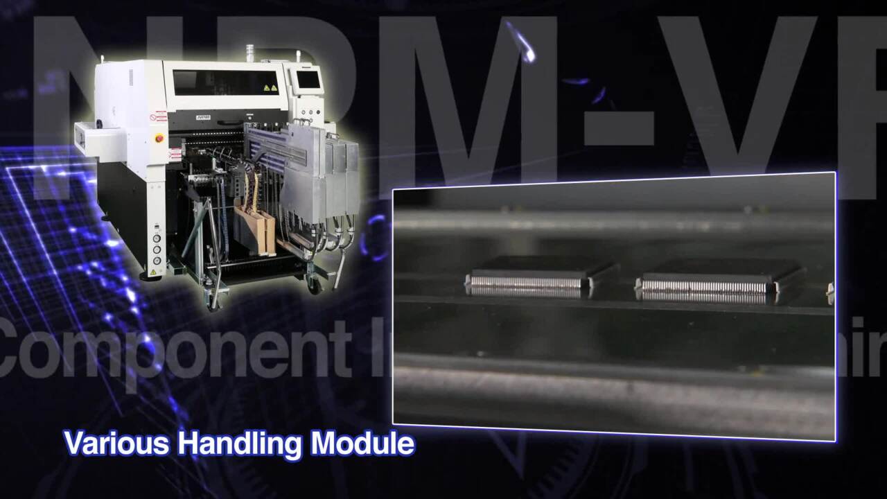
Various types of component supply
Various type of component supply units can be installed according to the component packaging
Supports stacable stick feeder, radial tape feeder, tray feeder and intelligent tape feeder.
High quality
Recognition correction and component inspection function
High quality and stable production is achieved with a two-camera configuration consisting of a head camera and a component camera.
- Head camera:
Recognizes PCB reference holes and PCB marks, and corrects PCB position and angle deviation. - Component camera:
Recognizes the lead or outline of a component during component handling, and corrects position and angle deviation.
Cut & clinch (optional)
Prevent component from falling off/floating on the PCB after insertion, and stabilizes the inserted state.
- Variable clinch pitch (2.5 ~ 40 mm)
-
Insertion error detection by piezoelectric element
Please select anvil conveyor specification. When this option is selected, SMT componenyts cannot be used.
Main Specifications
| NPM-VF | |
|---|---|
| PCB dimensions (mm) | Standard conveyor:L 50 mm × W 50 mm to L 510 mm × W 460 mm Anvil conveyor ( Option ):L 50 mm × W 50 mm to L 460 mm × W 400 mm |
| Max Speed | 3-station head:Max. 0.65 s / component 2-station head:Max. 0.9 s / component |
| Applicable components | Max. dimensions : L 130 mm × W 35 mm × H 60 mm ・ L 150 mm × W 38 mm × H 29 mm / Max. component mass : 200 g
|